A Tentec 1420 for fieldday use
Fieldday
From time to time I like to take some ham gear out in the field, and call it a one-person-fieldday.
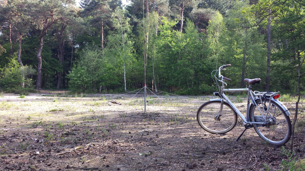
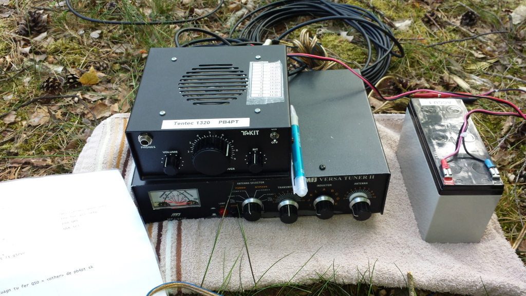
As a setup I typically use a fishing pole that holds a 20m vertical with some radials, a manual MFJ tuner
and a Tentec 1420 homebuild (kit) transceiver. As a power source I use a 12 Volt gel battery.
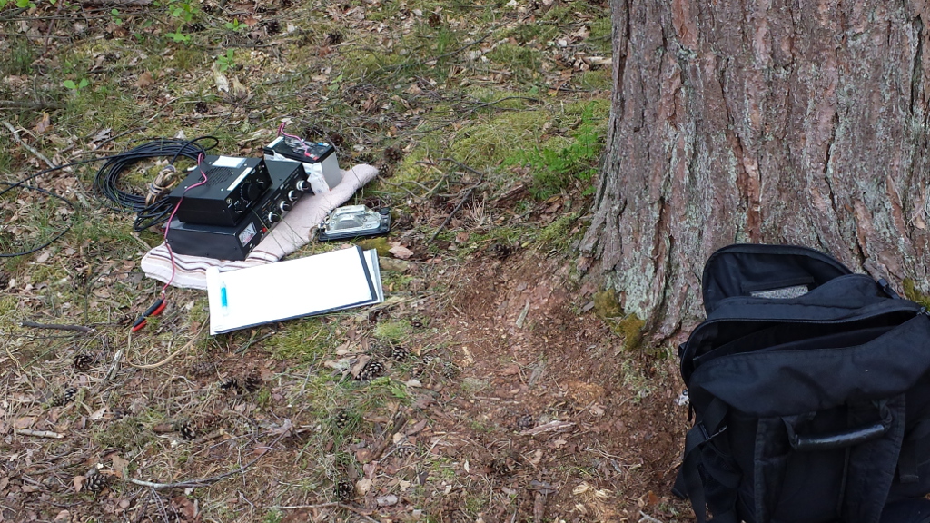
The pictures below give a rough idea of what the entire setup looks like. As you can see I can take the
entire setup with me in a backpack for a bikeride.
Aligning the Tentec 1420
As the settings of the Tentec 1420 were set a long time ago, with limited equipment, I recently decided to
redo the alignment of this transceiver. Part of this alignment was to get the pitch of the morse signal
during sending to 700Hz which I've got used to with my Yaesu FT-950 at home.
The procedure used for this alignment is given below (derived from the TenTec 1420 kit manual), as it may
help others going through the same procedure. The transceiver is designed to operate from 13.8 volts DC
for maximum output and receiver volume. When designing battery packs for portable operation, be mindful
that “slightly” lower voltages (such a s 11-12 Volt) will result in considerable reduction in RF output.
- Measure power consumption
- DC supply voltage (should: 13.8 V)
- Power consumption in Receive with no signal (35mA)
- Power consumption in Receive with S9 signal (80mA)
- Power consumption in Transmit (750mA)/LI>
- Align RIT control to make sure VFO operates at the same frequency at Receive and Transmit
- Connect counter probe to the side of R13 nearest Q4. I've actually used the hardware
frequency counter in my Rigol DS1054Z scope
- Key transmitter and note exact VFO frequency
- Unkey, adjust R46 shaft to same reading noted in transmit
- Mount RIT knob with its index stripe exactly at the center (12:00) mark on the panel/LI>
- Side tone pitch. To make sure you are transmitting on the same frequency as stations you
are hearing, L14 must be adjusted using a reference signal which can be heard on both the
Model 1420 reeiver and a second receiver. The reference signal can be actual 20 meter CW
activity or a source such as an RF signal generator. In my case I've used an ancient Advance
B4A signal generator, which took a warming up period of 1 hour before it was stable enough to
to this measurement.
- With the RIT control centered at 12:00 position, tune the 1320 receiver to the reference signal
at the audio pitch you generally prefer (700 Hz, measure on counter/scope – audio output).
- On the 2nd receiver, tune in the reference signal to the same audio pitch
- While keying the 1320 transmitter (using a dummy load), adjust L14 until your transmit signal
is the same pitch in the other receiver as the reference signal. This adjustment places your
transmit signal exactly on the other station’s frequency. (If you are concerned about which
sideband of your signal or the reference signal you are hearing in the other receiver, tune
both signals to a perfect “zero-beat” or null).
- General Receiver alignment
- Alignment of the receiver section consists of adjusting L6, L18, L7, L5 for maximum received
signal level or background noise. You can do this by ear or by observing the readings of an AC
voltmeter connected to the speaker terminals. As I still lack an AC volt meter, the scope was
used for this purpose, while connecting the receiver to a signal generator that was producing
a weak signal in the middle of the band.
- Transmitter Power check
- Connect 50 ohm dummy load or antenna with RF wattmeter and a key. If using an antenna, tune to
a clear frequency and use proper callsign ID. While keying the transmitter adjust L12 and L13
for maximum RF output. IF RF output is not at least 3 Watts, the coil windings may be spread too
far apart, compress them and recheck RF output. At 13.8V supply, my transmitter was producing
exactly 4 Watt. When dropping the supply to 12 Volt, power output reduces to just below 3 Watts.
- Also, make certain that your DC power source is capable of supplying 12-14V at 1A.
- Sidetone Adjustment
- Adjust trimmer R61 for preferred volume level.
The pictures below indicate my setup for measuring, while the paint tin contains a dummy load and some
cooling oil (paraffine) to absorb the produced RF energy.
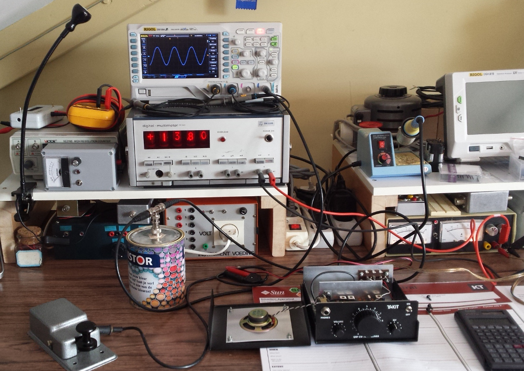
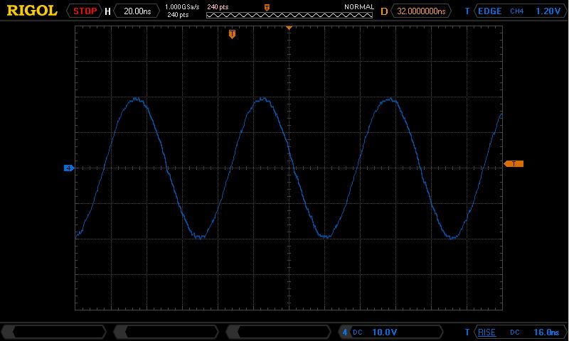
40 Volt peak-peak into 50 ohm, appears to be exactly 4 Watt.
After all the alignments were done, I've created a new table that cross reference the frequency dial reading
with the actual frequency in use.
| dail | frequency (MHz) |
|---|
| 1 | 13.997 |
| 2 | 14.007 |
| 3 | 14.031 |
| 4 | 14.038 |
| 5 | 14.045 |
| 6 | 14.052 |
| 6.5 | 14.055 |
| 7 | 14.057 |
| 7.5 | 14.060 |
| 8 | 14.063 |
| 9 | 14.068 |
| 10 | 14.071 |
As an end result I consider my Tentec transceiver much more fun to work with, and I'm still impressed by the
quality of this product (which is still available for sale, 2015).